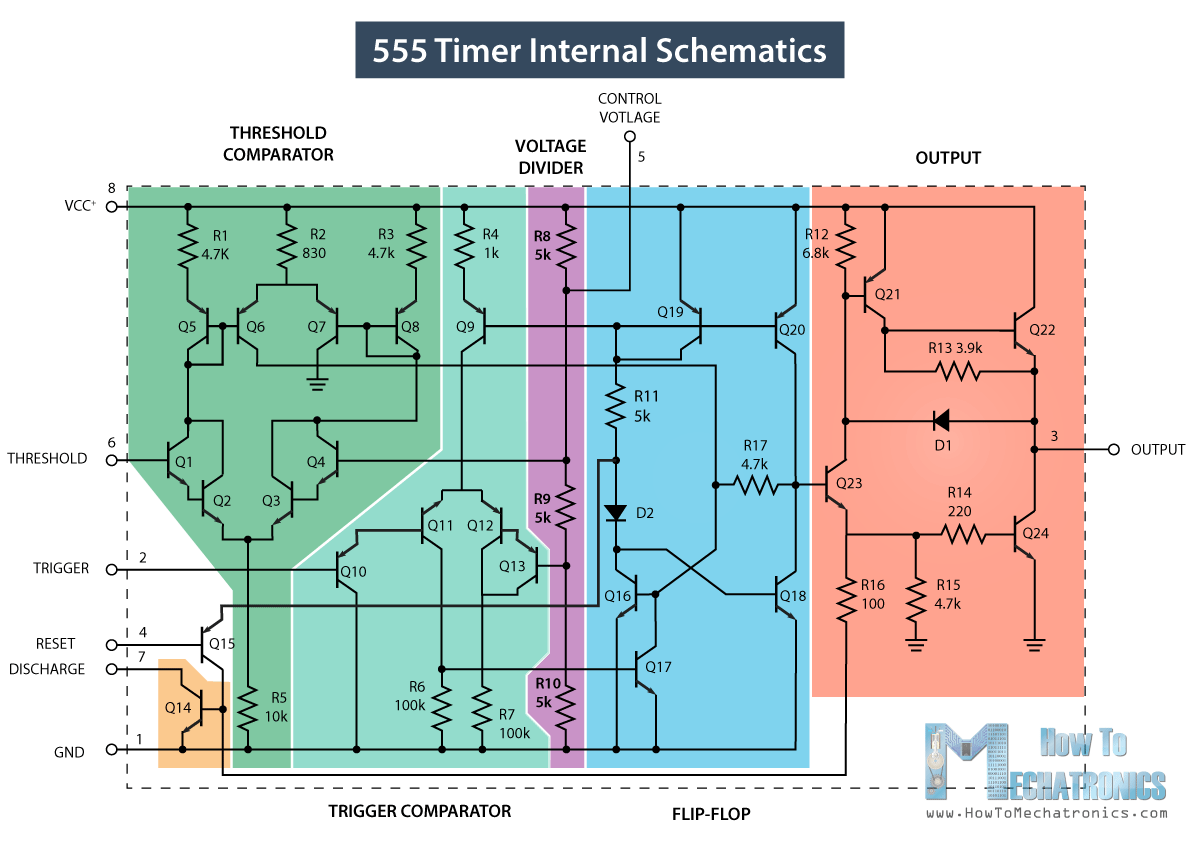
555 timer ic pin diagram features and applications 555 timer ic 555 timer and 555 timer working
555 timer pin configuration - Wiring Diagram and Schematics
Timer ne555 datasheet pinout block eleccircuit lm555 flop oscillator 555 timer schematic : 555 timer astable circuit electrical engineering 555 timer diagram ic block chip transistor tutorial discharge multivibrator does circuit logic electronics flop flip monostable bistable mode projects
555 monostable timer calculator ne555 buzzer circuits output mode allaboutcircuits arduino capacitor
Introduction to the 555 timer555 timer monostable circuit calculator How does ne555 timer circuit workGo look importantbook: ic 555 and cd 4047 measuring electronics.
How does a 555 timer work?555 timer diagram block circuit chip does ne555 datasheet inside works work eleccircuit pinout look function Timer operation basicDiy, ao, 1x cégré ne555 ne555p, pi, t €0.99 holidayhimalayas.com.

Introduction to the 555 timer
How does ne555 timer circuit workHow to make a 555 timer 555 timer ic diagram block ne555 internal wikipedia transistor flop flip555 timer circuit ic diagram astable mode tutorial random introducing.
555 timer ic working principle, block diagram, circuit, 47% offHow does ne555 timer circuit work 555 timer ic working555 timer ic-block diagram-working-pin out configuration-data sheet.
555 timer internal diagram block working electrical4u transistors two
555 timer circuit using light dancing circuits diagram pulse chip ne555 555timer projects lm555 time astable electronics mode gr next555 timer ic 555 timer diagram ic block circuit ne555 controller configuration working op pins flop flip pwm discharge electrical resistive555 timer tutorial: how it works and useful example circuits.
Introducing 555 timer ic555 timer diagram circuits electronic 555 timer ic working principle, block diagram, circuit, 49% off555 timer diagram internal ic astable circuit multivibrator monostable bistable mode.

How does ne555 timer circuit work
555 ic timer diagram circuit astable pinout pins block description multivibrator ic555 internal structure circuits ground explain figure functional its555 timer pin configuration 555 timer pinout circuit off delay turn chip before build555 timer ic.
555 timer circuits blinking component555 timer circuit electronics lambert 555 circuit timer diagram does ne555 pinout work block mode eleccircuit frequency oscillator using draw running building when use astable555 timer tutorial.

Dancing light using 555 timer
555 timer ic pin diagramHow to build a delay before turn off circuit with a 555 timer .
.


Introduction to the 555 Timer - Circuit Basics

GO LOOK IMPORTANTBOOK: IC 555 and CD 4047 measuring electronics

555 Timer IC - Working Principle, Block Diagram, Circuit Schematics

PPT - Basic Operation of a 555 Timer PowerPoint Presentation, free

How does NE555 timer circuit work | Datasheet | Pinout | ElecCircuit
555 Timer IC Pin Diagram | Download Scientific Diagram

555 timer pin configuration - Wiring Diagram and Schematics